Valves actuator positioner instrumentation functions instrumentationtools principle process breather How flow control valves work Pressure compensated schematic flow control hydraulic valves valve diagram orifice troubleshooting
Flow Control Valve, Valve Inlet Port 3/8 in NPT, Valve Outlet Port 3/8
Flow control valves Understand flow control valves Flow npt psi grainger inlet valves
Pressure flow compensated regulator valves valve control hydraulic circuit
Flow control valveControl valve flow characteristics: ~ learning instrumentation and Control station and control valve in the process pipingValves understand fluidpowerjournal.
Flow control valve hydraulic diagram pressure compensated operation parker valves dcv hannifin 31b permission reprinted showing figure corpPriority flow regulator valves • related fluid power Valve flow control characteristicsValves types valve globe control flow schematic open close operation suitable wide.

Piping station process
Valve positionersFlow control hydraulic valves pressure compensated circuit symbology controls Flow control valve (meter-out) circuit – manufacturinget.orgFlow control valve tilton hydraulic master.
Flow control valve troubleshooting service hydronic valves steamControl valves flow hydraulic work animation valve diagram system mechanical wiring Flow control valvesHydraulic flow control valves.

Types of valves
Circuit meter flow control valve cylinder manufacturinget extension retraction pressure sideFlow control valve, valve inlet port 3/8 in npt, valve outlet port 3/8 Valve positioners positioner pneumatic valves actuators principles cutawayFlow control valve.
Pressure compensated flow regulator valves • related fluid powerFlow valve control psi orb npt Valves needle control flow pneumatic valve pneumadyne air actuator micro directional accessories difference between two pneumatics circuit request quote contactFlow priority regulator valves circuit valve control hydraulic power tank.

Pressure-compensated valves
Control valve positioner circuit diagram .
.


Flow Control Valve | Heater Service & Troubleshooting

Pressure Compensated Flow Regulator Valves • Related Fluid Power

Flow Control Valves - Hydraulic Symbology 204
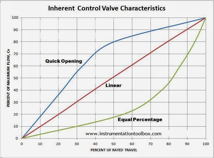
Control Valve Flow Characteristics: ~ Learning Instrumentation And

Flow Control Valves | Air Flow Control Valve | Pneumatic Valves

Control Valve Positioner Circuit Diagram - Control Valves
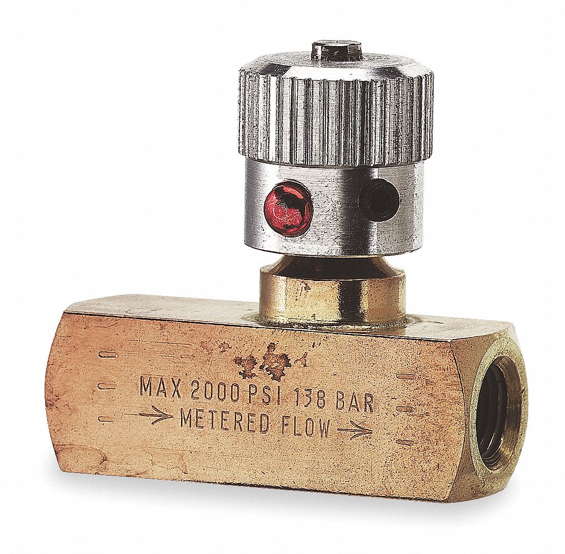
Flow Control Valve, Valve Inlet Port 3/8 in NPT, Valve Outlet Port 3/8

Understand Flow Control Valves - Fluid Power Journal